

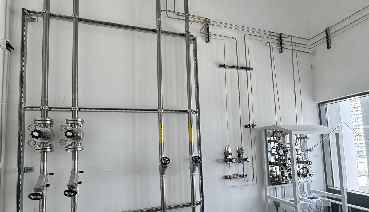
Summary: A laboratory gas pipeline system specification is the document that tells an installer which tubing material, joint type, installation practice and test to use for every gas line, and how each line will be inspected and accepted. A laboratory gas pipeline system is only as good as its specification, because the same building can be piped in copper with brazed joints, in bright annealed 316L stainless steel with compression fittings, or in electropolished 316L with orbital welds, at very different cost and purity.
A complete laboratory gas piping specification covers materials and joints gas by gas, installer and procedure qualification, site cleanliness, supports and labels, a test sequence with written acceptance criteria, inspection hold points and the records handed over. This guide explains each clause and the reasoning behind it.
- What a pipeline specification must control
- Materials gas by gas
- Tube sizes, wall thickness and ratings
- Joint types and how to specify them
- Installer and procedure qualification
- Site cleanliness, supports and labels
- Test sequence and acceptance criteria
- Inspection hold points
- Scope and interfaces
- Records at handover
- Common specification mistakes
- FAQ
What must a laboratory gas pipeline specification control?
A laboratory gas pipeline specification must control every decision that affects purity, safety and reliability and that an installer could otherwise make on price alone. In a laboratory gas piping system, those decisions are the tube material and finish, the joint type, the cleanliness of installation, the support and labelling of lines, the test methods and limits, and the documentation that proves the work was done.
The specification covers the distribution network between the gas source and the point-of-use panels: main lines, risers, branches, isolation valves and the connections to equipment. The gas room equipment and the point-of-use panels have their own specifications, but the interfaces between them, such as connection types and test boundaries, must be defined in the pipeline specification so that no section is left untested. Routing rules, typical line sizes and labelling practice are described on our laboratory gas pipeline system page; this guide concentrates on how to write them into enforceable clauses.
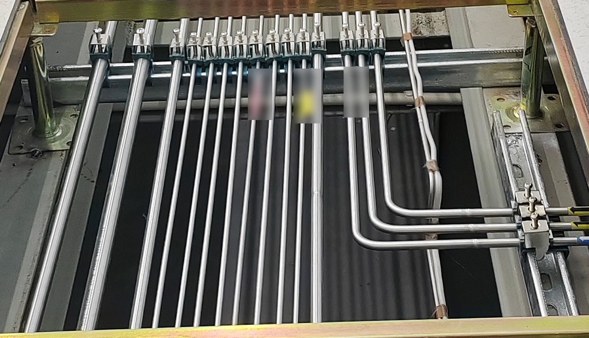
Which material should each laboratory gas line use?
The material of each laboratory gas line should be chosen by the gas and its purity class, not set once for the whole building. A single specification that requires electropolished stainless steel for every line wastes money on utility gases, while a specification that allows copper everywhere puts specialty and corrosive gases at risk.
| Gas group | Typical tubing | Typical joints | Notes |
|---|---|---|---|
| Utility gases: compressed air, general nitrogen, CO2 | 316L stainless steel or copper for medical and laboratory gas service | Compression fittings or brazed joints (copper) | Copper is brazed with an inert gas purge to avoid internal oxide scale |
| Carrier and calibration gases: helium, nitrogen, argon, hydrogen for GC, GC-MS, ICP | Bright annealed 316L stainless steel, cleaned and capped | Double ferrule compression fittings, or orbital welds on long runs | No polymer tubing except short final connections |
| Ultra high purity process gases | Electropolished 316L or VAR 316L | Orbital welds, metal gasket face seals at components | See the UHP gas delivery system guide |
| Corrosive gases: HCl, HBr, Cl2, NH3 | Electropolished 316L, often VAR or VIM-VAR | Orbital welds, face seals | Minimise joints; corrosion starts at surface defects and moisture |
| Oxygen and oxidising gases | Stainless steel or copper cleaned for oxygen service | Welded, brazed or compression joints with oxygen-compatible materials | Components and lubricants must be oxygen compatible; keep clean until connection |
| Flammable gases: hydrogen, methane | 316L stainless steel | Orbital welds preferred, minimum mechanical joints in concealed spaces | Fewer joints reduce leak points; route away from ignition sources |
Material certificates should be required for stainless steel tubing and fittings in high purity, corrosive and hazardous gas service, linked to the installed line by heat number where the project requires traceability. For utility gas lines, a certificate of conformity for the tube batch is often sufficient. The high purity tubing and weld fittings range covers 316L components for welded lines.
How should tube sizes, wall thickness and ratings be specified?
Tube sizes in a laboratory gas pipeline system should be specified by outside diameter and wall thickness for each line, taken from the sizing calculation, and the pressure rating of each tube and fitting should be confirmed against the design pressure with a margin. Writing only "1/4 inch line" leaves the wall thickness, and therefore the rating and the internal volume, to the installer.
- One measurement system per project: inch and metric tubing look similar but are not interchangeable, and mixing them leads to leaking compression joints. Where both are unavoidable, metric-to-inch adapters should be specified and labelled.
- Design pressure per line: state the maximum pressure each section can see, including regulator failure upstream, and fit relief protection where a section could be over-pressurised.
- Peak flow sizing: lines are sized from the peak simultaneous flow with an agreed growth margin and an allowed pressure drop; the calculation should be part of the design package.
- Bend radius and bending: specify bending with a tube bender to a minimum radius instead of fittings at every change of direction, because each fitting is a potential leak point.
Which joint types should be specified, and how?
Each joint type in a laboratory gas pipeline needs its own specification clause, because each fails in a different way. A specification that names the joint type without the method leaves the most important quality step undefined.
| Joint type | Where it is used | What the specification should require |
|---|---|---|
| Double ferrule compression fitting | Laboratory and carrier gas lines, equipment connections | Tube cut square and deburred, tube and fittings matched in size system, ferrules and nuts from one product family, make-up to the manufacturer's method, gap gauge check where provided |
| Orbital weld | UHP, corrosive, flammable and long welded runs | Qualified weld procedure, inert gas purge of the tube bore, test coupons at the start of each shift or set-up, numbered weld log, visual and internal inspection of a defined sample |
| Brazed joint (copper) | Utility and some laboratory gas lines in copper | Qualified brazers and procedure, inert gas purge during brazing, no flux inside the bore, cleaning after brazing |
| Metal gasket face seal | Components and connections that must be openable in UHP lines | New gasket at every make-up, clean handling, torque or make-up to the manufacturer's method |
| Threaded joint | Only at equipment ports where no alternative exists | Not allowed in the high purity gas path; sealant type specified where permitted |
The joint count is as important as the joint quality. Every joint is a potential leak, so a specification that requires bent tubing, long continuous runs and joints only where needed for installation or maintenance produces a more reliable system than one that allows fittings at every bend. The compression tube fittings range lists the unions, tees, elbows and bulkhead fittings typically used.

How should installers and procedures be qualified?
Installer qualification is the clause that most directly decides whether a laboratory gas pipeline passes its tests the first time. The specification should require written procedures for each joint type and evidence that the people making the joints are qualified for those procedures.
- Welding: a qualified welding procedure for each tube size and material, welder or welding operator qualification records, and test coupons made and inspected before production welding begins on each set-up.
- Brazing: a brazing procedure and brazer qualification for copper systems, including the purge method used during brazing.
- Compression fittings: installer training in the fitting manufacturer's make-up method and gap gauge use.
- Clean practice: training in capping, clean handling, oxygen service cleanliness and the reasons behind each rule.
- Testing: testers trained in pressure testing safety, leak testing methods and the recording of results, with calibrated instruments identified on each record.
For process piping, ASME B31.3 is widely used to define welding qualification, examination and testing requirements, and for medical gas systems NFPA 99 sets installer qualification and verification requirements in the United States. The project should name which standard applies to each part of the system and which local code takes precedence.
What should the specification say about site cleanliness, supports and labels?
Site cleanliness clauses protect the inside of a laboratory gas pipeline from the moment tubing arrives until the system is handed over. Tubing should be delivered capped and stored off the floor in a clean area, cut and prepared with tools reserved for clean tube, and capped immediately after every operation. Completed sections should be kept under a slight positive pressure of clean inert gas until they are tested.
Support clauses keep lines straight, protected and free from stress on joints. The specification should require supports at regular intervals suited to the tube size, supports at every change of direction and on both sides of valves and heavy components, isolation between stainless steel and dissimilar metal supports where corrosion could occur, and protection where lines pass through walls and floors, with fire-stopping where required.
Labelling clauses make the system safe to work on for its whole life. Every line should be labelled with the gas name and flow direction at regular intervals, at both sides of walls and at every valve, and every isolation valve should carry a tag that matches the isolation schedule. Colour codes and label formats should follow the site standard or the applicable national standard.
What is the test sequence, and what are the acceptance criteria?
The test sequence for a laboratory gas pipeline system should be written into the specification with a method and an acceptance criterion for every step, because a test without a limit cannot be failed. The steps are performed in order, section by section, before lines are concealed and again on the completed system where required.
| Step | Method | Typical acceptance criterion |
|---|---|---|
| 1. Visual inspection | Routes, supports, labels, joints and drawings checked | Installation matches the drawings; no unsupported joints or damaged tube |
| 2. Blowdown | Lines blown through with clean dry inert gas | No visible debris or moisture at the outlets |
| 3. Pressure test | Pneumatic test with clean dry inert gas above design pressure; ASME B31.3 uses 110 percent of design pressure for pneumatic tests | No failure, and no pressure loss beyond the agreed limit, corrected for temperature, over the hold period |
| 4. Leak test | Leak detection fluid at every joint for general service; helium mass spectrometer for high purity and hazardous lines | No detectable leak by the specified method and sensitivity |
| 5. Standing pressure test | Completed system held at working pressure, often for 24 hours | Pressure change within the agreed limit after temperature correction |
| 6. Cross-connection check | Each gas introduced in turn and every outlet checked | Correct gas at every outlet, no gas at outlets of other lines |
| 7. Purge | Lines purged with the service gas or high purity inert gas | Purge volume or moisture reading as specified |
| 8. Purity test, where specified | Moisture, oxygen, particles or composition measured at outlets | Limits agreed for each gas and purity class |
Pressure tests on gas lines are pneumatic, not hydrostatic, because water left in a gas line is difficult to remove and contaminates the gas. Pneumatic tests store energy in compressed gas, so the specification should require a test procedure, exclusion of people from the test area during pressurisation and relief protection on the test supply.
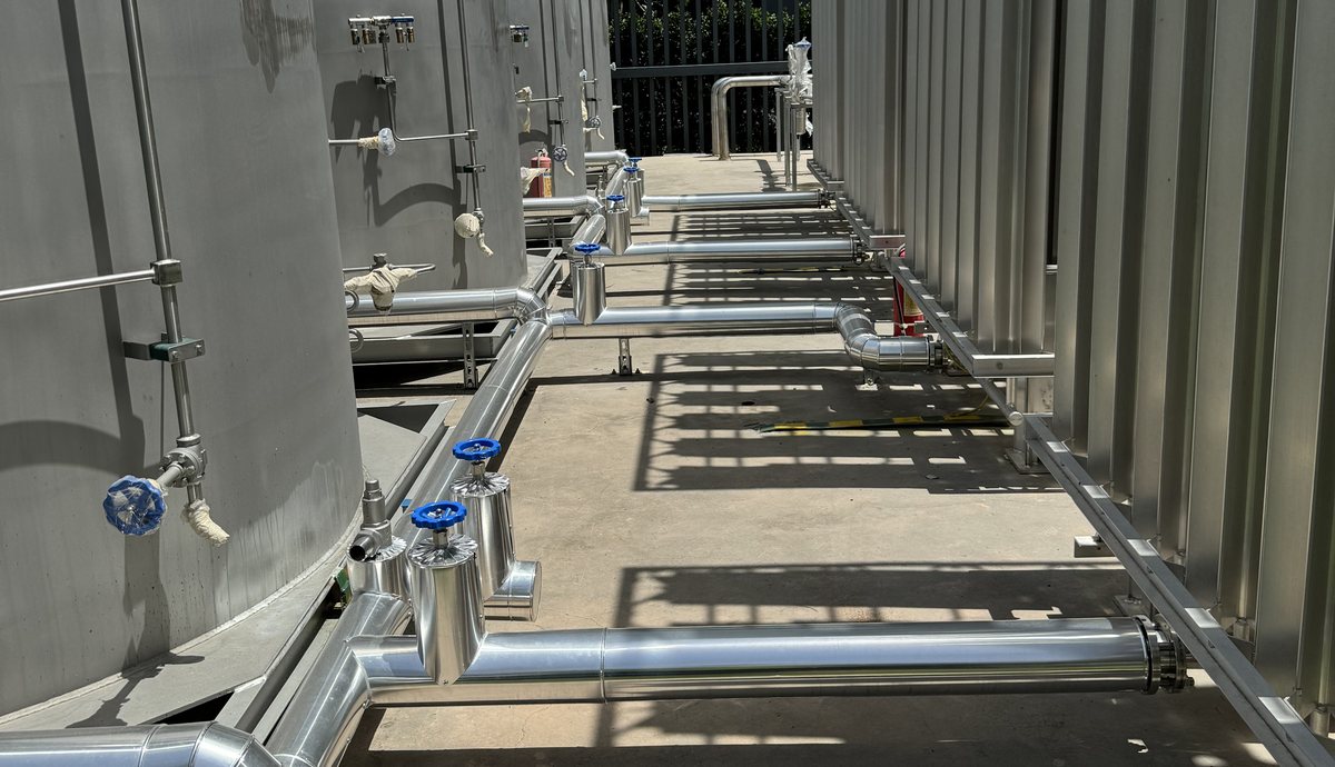
Which inspection hold points should be included?
Inspection hold points are stages at which work stops until the client or their engineer has inspected and accepted it. Hold points matter most where later work will hide earlier work, such as ceilings closing over gas lines or insulation covering joints.
| Hold point | What is inspected |
|---|---|
| Material receipt | Tube, fittings and valves against the specification; certificates; capping and packaging |
| First welds or brazes | Procedure, coupons and first production joints before full production starts |
| Before concealment | Routes, supports, labels and pressure test of each section before ceilings, walls or insulation close |
| Leak test of high purity lines | Helium leak test witnessed on selected or all sections |
| System tests | Standing pressure test, cross-connection check and purge on the complete system |
| Handover | Records, as-built drawings, labels and isolation schedule checked against the installation |
How should pipeline scope and interfaces be divided?
A laboratory gas pipeline crosses the work of several trades, so the specification should state who provides each interface and where the gas contractor's test boundary starts and ends. Unclear interfaces are a common cause of untested sections, duplicated prices and late changes.
| Interface | Typical owner | What the pipeline specification should state |
|---|---|---|
| Wall, floor and ceiling penetrations | Building contractor | Sleeve sizes and positions, fire-stopping responsibility |
| Unistrut and support steel | Gas contractor or mechanical contractor | Who supplies, who fixes, support spacing and material |
| Gas room equipment connection | Gas contractor | Connection type at the manifold outlet and the first isolation valve |
| Point-of-use panels and outlets | Gas contractor or laboratory furniture supplier | Panel positions, connection type and who tests the final connection |
| Instrument connection | Instrument supplier or laboratory | The outlet fitting provided and the boundary of the gas contractor's test |
| Alarm and shut-off wiring | Electrical contractor | Signal list, cable routes and who tests each alarm |
The test boundary should be drawn on the pipeline drawings. Every section between two boundaries needs a named contractor responsible for testing it, so that the final connections to equipment and instruments are tested as carefully as the main lines.
Which records should be handed over?
The records of a laboratory gas pipeline system must outlive the project, because the system will be maintained and changed by people who did not build it. The specification should list each record and its format before work starts.
- As-built drawings showing every line, valve, joint location where specified, and every change made on site
- Isolation schedule listing each valve, the section it isolates and its tag number
- Test records for every section: method, test medium, pressure, duration, instrument, result, date and signatures
- Weld logs and coupon results for welded lines, and brazing records for copper systems
- Material certificates linked to lines where traceability is required
- Purge and purity records where specified
- Operating and maintenance instructions, and records of training given
LGS hands over these records with every installation; the handover package and site testing are described on the installation page and the document types on certifications and quality documents.
What are the most common pipeline specification mistakes?
- One material for every gas. Specify by gas and purity class to avoid over- or under-specification.
- Joint type without method. "Compression fittings" or "welded" is not enough; define the procedure and inspection.
- Tests without limits. Every test needs a method, a duration and an acceptance criterion.
- No hold point before concealment. Lines closed into ceilings before testing are expensive to reopen.
- Mixed inch and metric tubing. Similar sizes look interchangeable but leak when mixed.
- Hydrostatic testing of gas lines. Water left in gas lines contaminates the gas for a long time.
- Records requested at the end. Weld logs and test records must be produced as the work proceeds.
Frequently asked questions
Is stainless steel or copper better for a laboratory gas pipeline?
Stainless steel 316L is better for high purity, specialty, corrosive and flammable gases because it is cleaner, more corrosion resistant and suits welded and compression joints. Copper is acceptable for many utility gases and is widely used in medical and laboratory gas systems when it is cleaned and brazed under an inert gas purge.
Can compression fittings be used in a laboratory gas pipeline?
Compression fittings can be used in laboratory and carrier gas pipelines when the tube is cut square and deburred, the fittings and tube are from matched size systems and the fittings are made up to the manufacturer's method. Ultra high purity and corrosive gas lines normally use orbital welds and face seal joints instead.
What test pressure is used for a laboratory gas pipeline?
The test pressure depends on the design pressure and the applicable standard. For process piping, ASME B31.3 specifies a pneumatic test at 110 percent of design pressure, and many projects add a standing pressure test at working pressure, often for 24 hours, to confirm that the completed system holds pressure.
Why are gas pipelines not tested with water?
Gas pipelines are tested pneumatically with clean dry inert gas because water left inside a gas line is very difficult to remove completely. Residual moisture contaminates the gas, can corrode the tubing and can disturb sensitive instruments for a long time after commissioning.
How often should labels be placed on laboratory gas lines?
Labels should be placed at regular intervals along each line, on both sides of walls and floors, at every valve and at every branch, so that the gas and flow direction can be identified from any point where someone might work on the line.
Who should witness pipeline tests?
Pipeline tests should be witnessed by the client's engineer or a nominated representative at the hold points defined in the specification, especially pressure tests before concealment and leak tests on high purity lines. The tester and witness sign each test record.
Get a laboratory gas pipeline system specified and built by LGS
LGS writes pipeline specifications, supplies 316L tubing, weld fittings and compression fittings, and installs and tests complete laboratory gas pipeline systems with weld logs, test records and as-built drawings. Send your gas list, floor plans or existing specification to info@labgassystem.com, and our engineers will review it and propose routes, materials and a test plan.
Explore more on the LGS website: laboratory gas pipeline systems, gas distribution systems, tubing and fittings, installation services and installed projects, or contact our engineering team.