

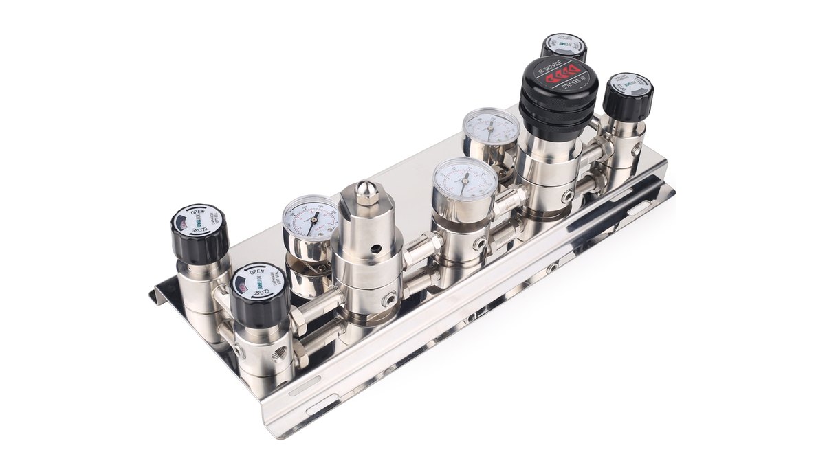
Summary: Laboratory gas equipment is the hardware that controls gas between the source and the instrument: pressure regulators that reduce and hold pressure, changeover manifolds that switch between cylinders, valves that isolate, meter and protect, filters that remove particles, gauges and transducers that show pressure, and panels that combine these parts on one plate. Each type of laboratory gas equipment works on a simple principle, and knowing that principle explains most datasheet terms and most faults.
The datasheet terms that matter most for laboratory gas equipment are droop, creep, supply pressure effect and flow coefficient (Cv) for regulators and valves, plus leak rate, wetted materials and surface finish for purity. This guide explains how each piece of equipment works, how to read those terms and how to recognise common problems before they stop an instrument.
- Where each piece of equipment sits
- How a pressure regulator works
- Droop, creep and supply pressure effect
- Single stage or dual stage
- How changeover manifolds switch
- Valve types and their jobs
- Filters, gauges and transducers
- Panels and gas sticks
- Reading a datasheet
- Matching materials to the gas
- Common faults and their causes
- FAQ
Where does each piece of laboratory gas equipment sit in the gas path?
Laboratory gas equipment is arranged along the gas path in a fixed order: cylinder connection, changeover, first-stage regulation, distribution and isolation, and final regulation at the point of use. Each piece of equipment must be rated for the pressure at its position, which is highest at the cylinder and lowest at the instrument.
| Position | Equipment | Typical pressure |
|---|---|---|
| Cylinder connection | Pigtail, check valve, cylinder isolation valve | Full cylinder pressure, often up to 200 to 300 bar |
| Changeover | Changeover manifold or automatic changeover panel | Cylinder pressure on the inlet side |
| First-stage regulation | Source regulator or pressure control panel | Reduces cylinder pressure to distribution pressure |
| Distribution and isolation | Tubing, fittings, diaphragm or ball valves, filters | Distribution pressure |
| Point of use | Line regulator, gas stick, gauge, outlet valve | Final instrument pressure |
Matching equipment across the path is as important as choosing each part well. A regulator rated for 200 bar inlet must never be fitted where it can see 300 bar, a valve with a small flow coefficient can starve a high-flow instrument even when the regulator is correct, and a polymer seal chosen for an inert gas may fail on a corrosive one. The laboratory gas equipment overview includes a selection table by task and typical rating.
How does a laboratory gas pressure regulator work?
A laboratory gas pressure regulator works by balancing two forces on a diaphragm: a spring that the user adjusts with the knob, and the outlet gas pressure pushing back against it. When outlet pressure falls below the set point, the spring pushes the diaphragm down and opens a poppet against its seat, letting more gas through; when outlet pressure rises to the set point, the diaphragm lifts and the poppet closes.
The quality of a regulator depends on four parts: the diaphragm, the seat, the poppet and the body. Metal diaphragms, usually stainless steel or a nickel alloy, are used in high purity and ultra high purity regulators because they do not outgas or let air permeate into the gas. Seats are made from polymers such as PCTFE, PTFE or polyimide chosen for the gas and temperature. Bodies are brass for general laboratory service and 316L stainless steel for high purity, specialty and corrosive gases.
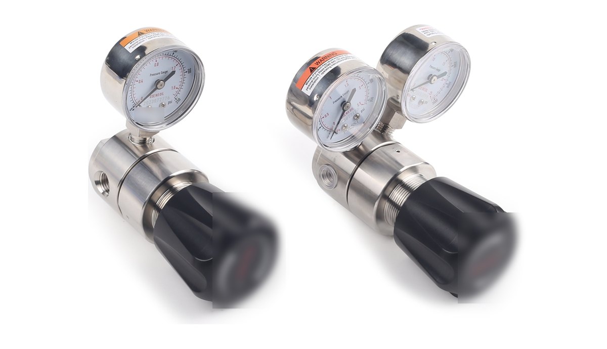
A regulator is a control device, not a shut-off device. The seat of a regulator is designed to control flow, not to provide tight isolation over long periods, so every regulator should have an isolation valve downstream, and lines should be isolated with valves rather than by turning the regulator knob fully out. The ultra high purity regulators and panel and line regulators pages list the ratings of each series.
What do droop, creep and supply pressure effect mean?
Droop, creep and supply pressure effect are the three behaviours that describe how well a regulator holds its set pressure, and each has a different cause and a different remedy.
| Term | What happens | Main cause | Remedy |
|---|---|---|---|
| Droop | Outlet pressure falls as flow increases | The spring extends as the poppet opens, so the force on the diaphragm drops | Choose a regulator sized for the flow, or one with a flatter flow curve |
| Creep | Outlet pressure rises slowly when there is no flow | The seat does not close completely, often because of a particle or seat damage | Upstream filtration, clean installation, seat replacement |
| Supply pressure effect | Outlet pressure changes as inlet pressure changes, typically rising as a cylinder empties | Inlet pressure acting on the poppet area | Dual stage regulation, or a regulator with a low supply pressure effect |
Creep is the behaviour that most often damages instruments. A regulator that creeps lets outlet pressure rise towards inlet pressure while the instrument is idle, which can over-pressurise low-pressure components. Relief protection downstream of high-pressure regulators, upstream particle filters and clean installation all reduce the risk.
Gas also cools when it expands through a regulator, an effect known as Joule-Thomson cooling. For most gases at laboratory flows the cooling is small, but carbon dioxide and nitrous oxide at high flow can cool enough to freeze moisture or form solid particles at the seat, which is why high-flow regulators for those gases are sometimes heated.
Should a laboratory use a single stage or a dual stage regulator?
A single stage regulator reduces pressure in one step and suits applications where the inlet pressure is stable or where small changes in delivery pressure are acceptable. A dual stage regulator reduces pressure in two steps inside one body, so the second stage sees an almost constant inlet pressure and the delivery pressure stays stable from a full cylinder to an almost empty one.
The choice depends on where the regulator sits and how sensitive the instrument is. A single stage regulator is a good choice as a line regulator downstream of a manifold or cabinet, because the line pressure feeding it is already stable. A dual stage regulator is the better choice directly on a cylinder that feeds a pressure-sensitive instrument, such as a gas chromatograph, or for toxic and pyrophoric gases at low flow, where an unattended rise in pressure is unacceptable. Two single stage regulators in series, one at the source and one at the point of use, give the same stability across a building.
How does a gas changeover manifold switch between cylinders?
A gas changeover manifold connects two cylinders or cylinder banks to one regulated outlet and transfers supply from the empty side to the full side. The switching method defines the type of manifold and how much operator attention it needs.
- Manual manifold: the operator watches the pressure gauge and opens the reserve side when the duty side is empty. Manual manifolds suit gases that can tolerate a short interruption.
- Semi-automatic manifold: two regulators or a changeover valve are set so that the reserve side takes over automatically when the duty side pressure falls below a threshold. After the empty cylinders are replaced, the operator resets the manifold so that the new cylinders become the reserve.
- Fully automatic manifold: pressure sensors and actuated valves switch sides, signal which side is in use, raise an alarm when a side is empty and can report status remotely, with no reset needed.
Every changeover produces a small pressure step at the manifold outlet, because the two sides are set at slightly different pressures. A point-of-use regulator downstream absorbs that step, so sensitive instruments should never be fed directly from a manifold without final regulation. The central laboratory gas supply planning guide explains how to choose the changeover method for each gas.
Which valve types are used in laboratory gas systems, and what does each do?
Each valve type in a laboratory gas system has one main job, and using a valve outside its job is a common cause of leaks and purity problems.
| Valve type | Main job | Where it is used |
|---|---|---|
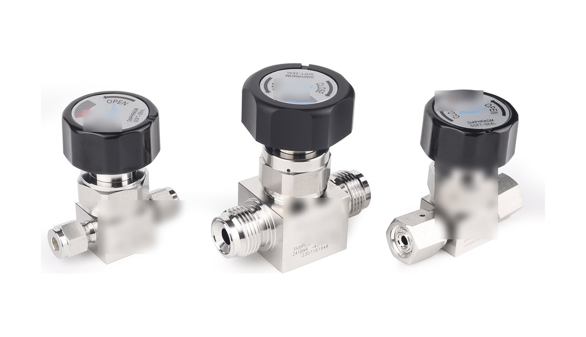
| Diaphragm valve | Isolation with no packing in contact with the gas | High purity and UHP lines, toxic and corrosive gases, cabinets and VMBs |
| Ball valve | Fast quarter-turn isolation with visible position | Utility gases, vents, test points, laboratory lines |
| Needle valve | Fine flow adjustment and metering | Purge flows, sampling, instrument bypasses |
| Check valve | Prevent backflow; opens at a set cracking pressure | Cylinder connections, purge inlets, mixed gas panels |
| Relief valve | Protect a section from over-pressure | Downstream of high-pressure regulators, trapped liquid sections |
| Excess flow valve | Close automatically if flow exceeds a limit | Hazardous gas sources, to limit release from a broken line |
Diaphragm valves are the standard isolation valve on high purity lines because a metal diaphragm separates the gas from the actuator, so there is no sliding seal or packing in the gas path, the internal volume is small and the valve purges quickly. Ball and needle valves have packing around the stem, which is acceptable for utility service but is a potential leak and contamination point on high purity lines. The instrument valves and filters range includes ball, needle and check valves and in-line filters.
What do filters, gauges and pressure transducers do?
An in-line gas filter protects regulators, valves and instruments from particles shed by cylinders, tubing and fittings. Filters are rated by the size of particle they retain, typically from about 0.2 to 20 micrometres for laboratory service, and the right rating balances protection against pressure drop and service life. A filter upstream of each critical regulator reduces seat damage and creep.
A pressure gauge shows pressure locally without power. The gauge range should be chosen so that normal working pressure falls in the middle part of the scale, which gives a readable indication and protects the gauge from constant full-scale stress, and dual bar and psig scales avoid conversion errors. The pressure gauges page lists dial sizes and ranges.
A pressure transducer converts pressure into an electrical signal for alarms, changeover control and remote monitoring. Transducers have smaller internal volumes than dial gauges, which helps purging on high purity lines, and they allow low-pressure alarms to reach the building management system so that a falling supply is noticed before the instrument stops.
What are point-of-use panels and gas sticks?
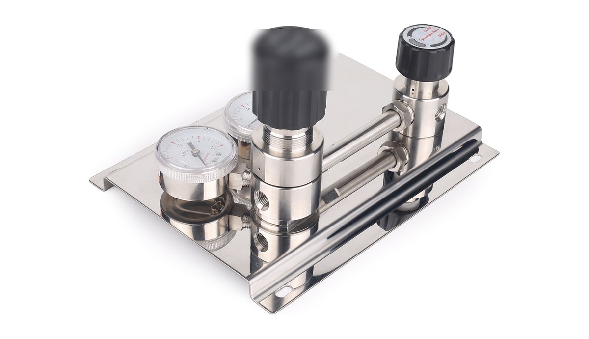
A point-of-use panel is a wall or bench mounted assembly that gives an instrument its own final regulator, gauge and isolation valve, so that no two instruments share pressure control. A gas stick is a compact version of the same idea, often with one to three outlets, used where several instruments in one room take the same gas at similar pressures.
Panels and sticks standardise how gas is presented to users. When every room uses the same panel layout, labels and valve positions, users and service engineers make fewer mistakes, and spare parts are common across the building. Pre-assembled panels are also tested in the workshop before delivery, which reduces joints made on site. LGS builds pressure control panels and gas sticks for one or two cylinders and for line pressure control.
How do you read a laboratory gas equipment datasheet?
A laboratory gas equipment datasheet should state the ratings and materials that decide whether a component suits a position in the gas path. The terms below appear on most regulator, valve and fitting datasheets.
| Datasheet term | Meaning | Why it matters |
|---|---|---|
| Maximum inlet pressure | Highest pressure the component may see at its inlet | Must exceed the full cylinder or line pressure at that position |
| Delivery pressure range | Range of outlet pressures a regulator can be set to | Choose a range where the set point falls in the middle, not at the ends |
| Flow coefficient (Cv) | A measure of flow capacity through a valve or regulator | A Cv that is too small limits flow and causes droop at peak demand |
| Leak rate | Maximum leakage, usually measured with helium | Defines suitability for high purity and hazardous service |
| Wetted materials | Materials in contact with the gas: body, diaphragm, seat, seals | Must be compatible with the gas and the purity class |
| Surface finish (Ra) | Roughness of internal wetted surfaces | Smoother electropolished surfaces adsorb less moisture and purge faster |
| Connections | Inlet and outlet connection types and sizes | Must match the tubing, fittings and cylinder valve outlets used |
| Operating temperature | Allowed temperature range for the component | Affects seat and seal materials, especially for heated or outdoor service |
Cylinder connections deserve special attention. Cylinder valve outlets are standardised by gas group in national standards, so that, for example, an oxygen regulator cannot be connected to a flammable gas cylinder. A regulator must always use the cylinder connection specified for the gas, and adapters between connection types should not be used.
How do you match equipment materials to the gas?
Every wetted material in a piece of laboratory gas equipment must be compatible with the gas it carries, because an incompatible body, diaphragm, seat or seal can corrode, swell, release particles or, with oxygen, become an ignition risk. Material compatibility is checked for each gas, not for the system as a whole.
| Gas service | Typical body material | Seat and seal considerations |
|---|---|---|
| Inert and general laboratory gases | Brass or 316L stainless steel | Common polymer seats such as PCTFE or PTFE are suitable |
| High purity carrier and calibration gases | 316L stainless steel | Metal diaphragm; seats chosen for low outgassing |
| Corrosive gases | 316L stainless steel, often VAR or electropolished | Seats and seals resistant to the specific gas; nickel alloy diaphragms where needed |
| Oxygen and oxidisers | Brass or stainless steel cleaned for oxygen service | Oxygen-compatible seats and lubricants only; parts kept clean until installation |
| High temperature service | 316L stainless steel | High temperature seat materials such as polyimide where the rating requires |
Calibration gas mixtures add one more consideration: some reactive components, such as low concentrations of hydrogen sulphide or nitric oxide, can adsorb onto unsuitable surfaces and change the concentration delivered to the analyser. For those mixtures, stainless steel regulators and lines with low internal volume and appropriate surface treatment are preferred, and the line should be conditioned with the mixture before calibration.
When the gas list changes, equipment compatibility should be rechecked. A regulator or panel that was correct for nitrogen may not be suitable for a new corrosive gas, even if the pressure ratings are the same.
What are the most common laboratory gas equipment faults?
Most laboratory gas equipment faults show up as a pressure that will not stay where it is set, and each symptom points to a likely cause.
| Symptom | Likely cause | Typical action |
|---|---|---|
| Outlet pressure rises when the instrument is idle | Regulator creep from a particle or damaged seat | Isolate, replace or service the regulator, add upstream filtration |
| Pressure falls when the instrument starts | Droop, or a regulator, valve or line too small for the flow | Check Cv and line size against peak flow |
| Pressure slowly rises as the cylinder empties | Supply pressure effect of a single stage regulator | Use a dual stage regulator or add point-of-use regulation |
| Frost or ice on the regulator | Joule-Thomson cooling at high flow, often with CO2 or N2O | Reduce flow per regulator, use a heated regulator |
| Pressure falls overnight with no use | A leak downstream of the regulator | Leak check joints and valves, starting at recently changed connections |
| Gauge needle vibrates | Pulsating flow or an unstable regulator | Check regulator sizing; fit a snubber or replace the gauge if damaged |
Frequently asked questions
What is laboratory gas equipment?
Laboratory gas equipment is the hardware that stores, switches, regulates, distributes, isolates and measures gases between the gas source and the instrument. It includes gas cabinets, changeover manifolds, pressure regulators, control panels, valves, filters, gauges, tubing and fittings.
Can a pressure regulator be used to shut off gas?
A pressure regulator should not be used to shut off gas, because its seat is designed to control flow rather than to isolate tightly over long periods. Every regulator should have an isolation valve downstream, and lines should be isolated with that valve.
Why do high purity regulators use metal diaphragms?
High purity regulators use metal diaphragms because metal does not outgas, does not let air permeate into the gas and tolerates purging and cleaning better than elastomers. The result is lower contamination and faster purging of the regulator.
What does the Cv of a valve mean?
The Cv, or flow coefficient, is a measure of how much flow a valve or regulator passes for a given pressure drop. A component with a higher Cv passes more gas at the same pressure drop, so Cv must be checked against the peak flow of the instruments it serves.
How often should laboratory gas regulators be replaced?
Laboratory gas regulators should be inspected regularly and replaced or serviced when they show creep, unstable outlet pressure, leakage or damage, or at the interval set by the manufacturer and the site's maintenance plan. Regulators on corrosive gases usually need more frequent inspection.
Do I need a gauge or a pressure transducer?
A gauge gives a local reading without power and suits most panels and regulators. A pressure transducer is needed when pressure must trigger alarms, control automatic changeover or be monitored remotely, and many systems use both at critical points.
Choose the right laboratory gas equipment with LGS
LGS manufactures and supplies laboratory gas equipment for the whole gas path: gas cabinets, changeover manifolds, UHP and line regulators, pressure control panels, diaphragm, ball, needle and check valves, filters, gauges, tubing and fittings. Send your gas list, pressures and flows to info@labgassystem.com, and our engineers will recommend matched equipment and send datasheets and a quotation.
Explore more on the LGS website: all product families, pressure control equipment, valves and filters, tubing and fittings and the design guide, or contact our engineering team.